Table of Contents
Encoder
An encoder is a combinational circuit that converts multiple input signals into a coded binary output. It typically has “2^n” input lines and “n” output lines.
How it works
Encoders work by detecting which input is active and generating a corresponding binary code. For example, in a 4-to-2 encoder, if input 3 (binary “11”) is active, the output will be “11”.
Diagram

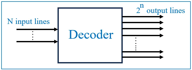
Decoder
A decoder is a combinational circuit that converts binary-coded inputs into a one-hot output, meaning only one output is active at a time.
How it works
A typical n-to-2^n decoder takes “n” binary inputs and activates one of “2^n” outputs. This is useful in memory addressing and demultiplexing.
Diagram
Adders
Adders are fundamental circuits used to perform binary addition.
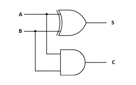
Half Adder
A half adder adds two single-bit binary numbers and outputs a sum and carry.
How it works
- Sum = A XOR B
- Carry = A AND B
Diagram
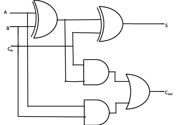
Full Adder
A full adder adds three input bits: two significant bits and a carry bit from the previous addition.
How it works
- Sum = A XOR B XOR Cin
- Carry = (A AND B) OR (Cin AND (A XOR B))
Diagram
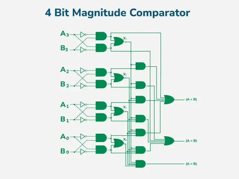
Comparator
A comparator compares two binary values and determines their relationship (equal, greater than, or less than).
How it works
A “n-bit” comparator has two inputs (A, B) and three outputs:
- A > B
- A < B
- A = B
Diagram
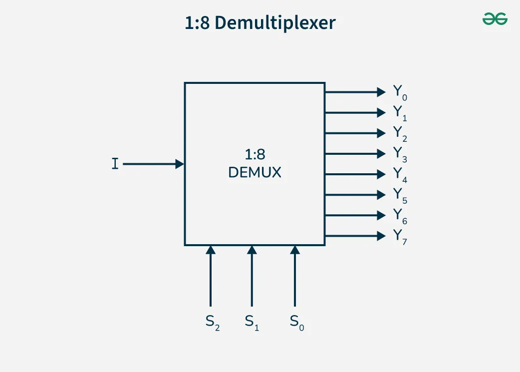
Demux
A demultiplexer (DEMUX) takes a single input and routes it to one of several output lines based on a selector input.
How it works
A 1-to-4 DEMUX has one data input, two selector inputs, and four outputs. The active output is determined by the selector inputs.
Diagram
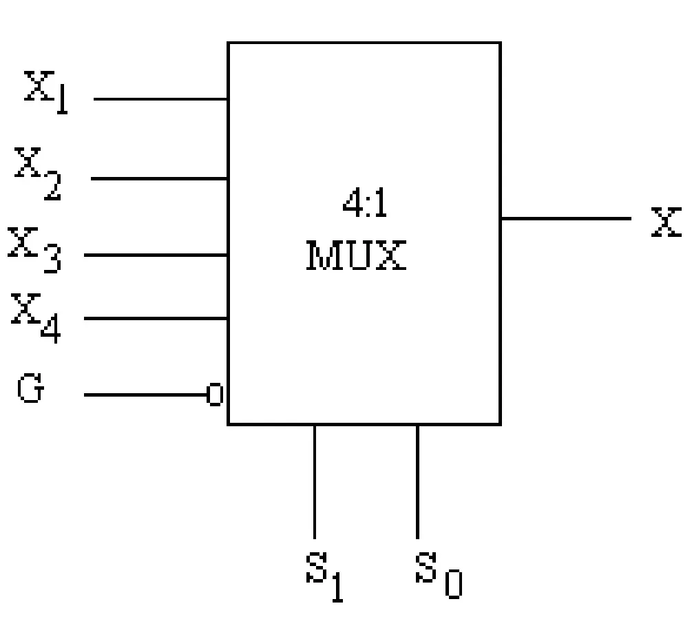
Mux
A multiplexer (MUX) selects one of several input signals and forwards it to a single output.
How it works
A 4-to-1 MUX has four inputs, two selector lines, and one output. The selector lines choose which input is transmitted to the output.
Diagram